|
|
|
|
Motherboard Study Notes Difference between AT and ATX:AT and ATX are different form factors for Computers. A form factor is the physical layout of the motherboard and its associated case. Changing the design of a motherboard usually means changing the design of the case. There are different variations on the AT design. There is the original AT, and the Baby AT form factor. The Baby AT design is simply a smaller version of the original AT design. It is therefore less expensive to make. A Baby AT motherboard can usually fit inside either a Baby AT case or a full AT case. However, an AT motherboard is too big to fit in a Baby AT case and it therefore must fit into an AT case only. The ATX is a newer design for motherboards and cases. The ATX design uses a different power supply connector and the ATX case cools internal components much more efficiently than its predecessor. In addition to ATX, there is also Mini ATX and Micro ATX. These are smaller versions of the ATX motherboards and cases which adhere to the ATX design specifications, but skimp on expandability. MotherBoard Architecture
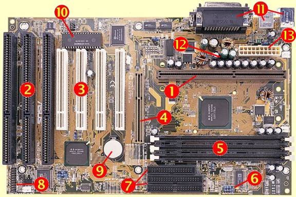
1. Slot 1 Connector - this is where your Pentium II or Pentium III processor fits in. If you are using a standard Pentium, AMD K5 or K6, a WinChip or an IBM/Cyrix processor then you will be using a Socket 7 (sometimes called Super 7 for the newer chips) motherboard and the connector will be as shown under the main diagram. 2. ISA (Industry Standard Architecture) Expansion Slots - used to add expansion cards such as sound cards and internal modems. This type of expansion slot has a 16-bit bandwidth with a frequency of 8MHz. They are the older interface and are now being phased out. 3. PCI (Peripheral Component Interface) Slots - these are a newer type of expansion slot than the ISA ones and more components are now making use of them instead of the older slots. They have a 16-bit bandwidth and a frequency of 33MHz. 4. AGP (Accelerated Graphics Port) - these are the newest standard in expansion slots, for use only with graphics boards. The newer model has a 64-bit bandwidth and a frequency of 66MHz. 5. Memory Slots - the ones shown are DIMM (Dual Inline Memory Module) slots. Used to add memory to your computer. 6. Jumpers - these are used to configure the options on your motherboard, such as processor voltages etc. The jumper is placed over two pins to cause an electrical connection. Your motherboard manual should tell you the settings for each jumper. 7. Floppy disk and Primary/Secondary IDE channels - used to interface you hard drives, CD-ROMS and floppy drives to your motherboard. The smaller connector is for the floppy drive, and the two larger ones are for IDE (Integrated Drive Electronics) devices such as hard drives and CD-ROM drives. Up to two devices can be used from one channel, so on this motherboard you could have up to two floppy drives with four IDE devices. 8. Front Panel Connectors - these connect to the lights on the front of your system case to notify you of hard disk access, power etc. If you have an ATX style case then a power connector also fits here. The wires that should be connected to these come from the front of the case. 9. Real-Time Clock battery - allows the computer to retain the time when it is powered down. Also retains configuration data from when you first set up your computer. 10. BIOS EEPROM (Basic Input-Output System Electrically Erasable Programmable Read-Only Memory) - The BIOS configures the system resources on your system, and performs the self-check procedure each time you switch on your PC. 11. Ports - connects external peripherals to the system such as a keyboard, mouse and printer. Most modern systems will have one each of PS/2 keyboard and mouse connectors, two serial ports, one parallel port and two Universal Serial Bus (USB) ports. 12. Voltage Regulation - these components help to regulate the power supply to prevent 'spikes' when the power is switched on. 13. Power Supply Connector - this is where the power arrives from your case's PSU (Power Supply Unit). The one shown on this board is an ATX style connector and supports extra features such as auto shut-down and energy saving compatibility. The older AT style connectors have only a single row of pins and don't support these extra features. |
|
|

Copyright © 2004 CertsBraindumps.com Inc. All rights reserved.
|